- 您现在的位置:买卖IC网 > Sheet目录39245 > LM1262NA/NOPB (NATIONAL SEMICONDUCTOR CORP) 3 CHANNEL, VIDEO PREAMPLIFIER, PDIP24
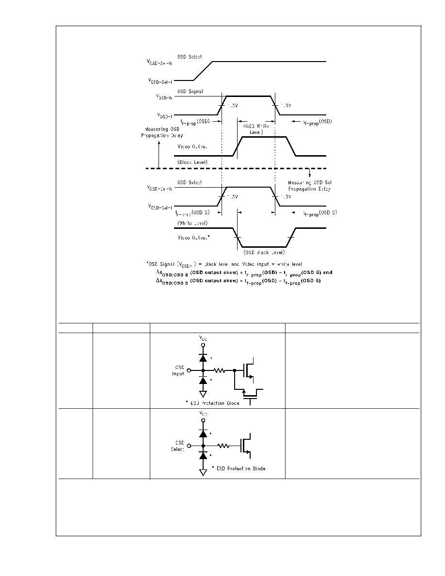
Timing Diagrams (Continued)
Pin Descriptions
Pin No.
Pin Name
Schematic
Description
1
2
3
Red OSD Input
Green OSD Input
Blue OSD Input
These inputs accept standard TTL or CMOS
inputs. Each color is either fully on (logic
high) or fully off (logic low). Unused pins
should be connected to ground with a 47k
resistor.
4
OSD Select
This input accepts a standard TTL or CMOS
input.
H = OSD
L = Video
Connect to ground with a 47k resistor if not
using OSD.
DS200404-12
FIGURE 3. OSD Output Skew
LM1262
www.national.com
8
发布紧急采购,3分钟左右您将得到回复。
相关PDF资料
LM129BH/883
1-OUTPUT TWO TERM VOLTAGE REFERENCE, 6.9 V, MBCY2
LM129BH
1-OUTPUT TWO TERM VOLTAGE REFERENCE, 6.9 V, MBCY2
LM12H454CIV
SPECIALTY ANALOG CIRCUIT, PQCC44
5962-9319501MXC
SPECIALTY ANALOG CIRCUIT
5962-9319502MYX
SPECIALTY ANALOG CIRCUIT, PQCC44
5962-9319501MYX
SPECIALTY ANALOG CIRCUIT, PQCC44
5962-9319501MXX
SPECIALTY ANALOG CIRCUIT
5962-9319502MXX
SPECIALTY ANALOG CIRCUIT, CQCC44
相关代理商/技术参数
LM1267
制造商:NSC 制造商全称:National Semiconductor 功能描述:150 MHz I2C Compatible RGB Video Amplifier System with OSD and DACs
LM1267NA
制造商:NSC 制造商全称:National Semiconductor 功能描述:150 MHz I2C Compatible RGB Video Amplifier System with OSD and DACs
LM1267NA/NOPB
功能描述:IC PREAMP RGB 150MHZ 24-DIP RoHS:是 类别:集成电路 (IC) >> 线性 - 视频处理 系列:- 产品变化通告:Product Discontinuation 07/Mar/2011 标准包装:3,000 系列:OMNITUNE™ 类型:调谐器 应用:移动电话,手机,视频显示器 安装类型:表面贴装 封装/外壳:65-WFBGA 供应商设备封装:PG-WFSGA-65 包装:带卷 (TR) 其它名称:SP000365064
LM1269
制造商:NSC 制造商全称:National Semiconductor 功能描述:110 MHz I2C Compatible RGB Video Amplifier System with OSD & DACs
LM1269DNA
制造商:Texas Instruments 功能描述:
LM1269DNA/NOPB
功能描述:IC PREAMP CMOS 110MHZ 24-DIP RoHS:是 类别:集成电路 (IC) >> 线性 - 视频处理 系列:- 产品变化通告:Product Discontinuation 07/Mar/2011 标准包装:3,000 系列:OMNITUNE™ 类型:调谐器 应用:移动电话,手机,视频显示器 安装类型:表面贴装 封装/外壳:65-WFBGA 供应商设备封装:PG-WFSGA-65 包装:带卷 (TR) 其它名称:SP000365064
LM1269NA
制造商:Texas Instruments 功能描述:Video Amplifiers 制造商:Texas Instruments 功能描述:-LIFETIME BUYS TIL 05/12
LM1269NA/NOPB
功能描述:视频放大器 RoHS:否 制造商:ON Semiconductor 通道数量:4 电源类型: 工作电源电压:3.3 V, 5 V 电源电流: 最小工作温度: 最大工作温度: 封装 / 箱体:TSSOP-14 封装:Reel